Sunday, November 30, 2014

Everything's better with Bluetooth

Edit (Dec 1 2014): This article was featured on Hackaday!
 ––––––––––––––––––––––––––––––––––––––––––––––––––
In my previous post I jerry-rigged an AUX input for my car's stereo. It worked alight, but as you can see in the photos it wasn't pretty -- I mean, who wants a cord dangling out of their tape deck tray?

I decided to scrap that and re-wire it with Bluetooth connectivity. I spent $15 dollars on the entire project (keys to remove stereo and the Bluetooth receiver) and now my phone plays through my car's stereo system without a hitch. Here's how I did it!

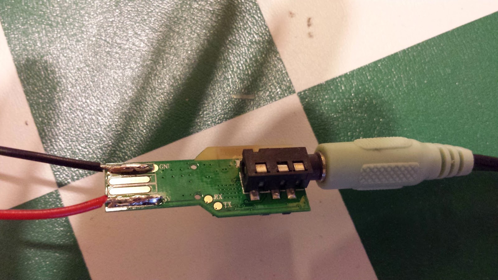
First I picked up one of these guys. The idea is that you power the unit via USB, plug in your stereo jack, and tether to it wirelessly with any Bluetooth enabled device. I'm not endorsing this brand in particular, it was just cheap and it does what I need.


Now what's with the USB connector? This device doesn't actually do anything in the way of data transfer via USB, so it must just be to power the unit. USB delivers 5 Volts, so I should be able to scrap the case and just find +5V / GND connections, right? Right.


You can make out the GND and 5V copper strips. Awesome, so to power this unit I just need a 5V DC source. I assumed my car's stereo has that somewhere, since it's filled with modern circuit boards.

Here's the other side of the unit. You can see the main controller and the antenna. Most of the soldering looks surprisingly decent.


OK, so now I'm ready to solder on some leads.


I used some flux on the copper strips first and then pre-tinned them and the wires -- I want this to be secure as hell.

Next up is testing. I hook up the power lines to my homemade variable power supply (yes, that used to be an alarm clock) and make sure I can play music from my phone to my room's speaker system.


Alright, that worked so I moved on to attaching an audio jack with open leads on one end, then commenced with liberal shrink-tubing.


Cover that up completely.


Alright, now what? Now what is crack that stereo system out!


So as I discussed in my last post, I found where the CD player sends left and right channel audio information out to the main amplifier. I hijacked those leads and connected them to the audio out of my Bluetooth receiver. Piece of cake. But now where the hell am I going to find 5 Volts? Look closely:


Now, do I know with absolute certainty that "P5V" with a solder test point next to it is a 5V DC lead? No. But am I going to go ahead and solder my cable there anyway? You betcha.

And here are the connections for Left and Right Channel audio.


Here's everything wired and sticking out hideously from the tape deck. For ground I soldered my cables directly onto the chassis.


Shove it in.


Finally I plugged this bad boy in and tested it. Worked like a damned charm, after fixing a couple of ground loop issues. Since I'm using my CD player's output, I have to trick the stereo system into thinking that a CD's playing. For that I burned an album with 10 hours of absolute silence. That did the trick.


So now I turn on my stereo, my phone automatically pairs to the Bluetooth receiver, and all of my phone's audio output (music, calls, etc) get routed through my car's speaker system. For the cost of a couple overpriced coffees.

That's it. Rock on and don't forget to be awesome.

Monday, November 10, 2014

Gave my car's stereo an AUX input


I bought a car recently. It runs like a dream, but the stereo's archaic -- no audio input for a phone, just tapes and CDs. While you can buy cheap tape-to-AUX converters, something about the coupling mechanism adds white noise to the signal. Instead of paying a bunch of money for a new stereo system, I cracked the sucker open and directly soldered in the connections.

Step 1: Lay down ten bucks for stereo removal keys and yank that machine out.


Step 2: Open her up.


Step 3: Find the pins to the CD player's ribbon cable output. Identify RCH (right channel), LCH (left channel), and find where ground is. In my case it wasn't labeled but I traced it to the pin between the left and right channel outputs to the ribbon cable.

From here, the CD player sends the audio signal to the main amplifier. This audio signal can be replaced with the audio output from a phone or mp3 player!


Step 4: Cut the three wires of the ribbon cable, solder in some of your own and extend them somewhere accessible.


Step 5: Carefully solder these leads to the male end of a male/female audio jack converter:


Step 6: Your stereo's now updated to the 21st century! Plug it in and blast some metal.


Still working on making it look prettier. Another improvement would be to use a bluetooth audio receiver module like this one, which can be completely encased in the stereo unit and accessed remotely. For the one linked to, the powering method is via USB (5V) -- so you'd need a buck converter to lower the car's native 12V DC or you could find a 5V line in the amplifier board (there's bound to be one somewhere).

Saturday, October 25, 2014

Uno Shield for Attiny85 Programming

 So the classic Arduino Uno runs the mammoth Atmega328P microcontroller, which has 23 general purpose I/Os and 32KB ISP flash memory (if you don't know, the Arduino platform and the entire board below is just a way to make programming the Atmega insanely convenient):


It's a crazy cool microcontroller, but let's face it -- it's way overkill for most applications. Nothing I've built with the Arduino has come close to using all 23 inputs/outputs.

You could save some money by building your own board to program the Atmega328P like I did in a previous post, but it's still often overkill to waste that many I/Os.

Enter the Attiny85:


It's Atmel's miniature version of the 328P, sporting only 6 general I/Os and 8kB of flash memory (but the same number of working registers). This is plenty of room for a lot of small projects, so I picked up a few of them.

So, how do you program them? We program the larger Atmega328P chips with the Arduino Uno board, and as it turns out you can use the same board to program the Attiny85s, with a bit of work.

Here's the guide I used to configure the Uno to act as an ISP (In-System Programmer) to program the 'tiny, but I wanted to build something more permanent -- like a shield that I could attach to the Uno and quickly pop in/out the 'tiny processors.

Here's what I came up with:


It connects to the Uno's pins via some male headers, and ends up snapping on to look something like this:


The Attiny85 fits into the IC holder:


And after some configuring you can program it just like its larger brother. I tested it with the easy Blink program:


At some point I'll build something a bit more complicated with it, but...


Wednesday, October 15, 2014

Danger!

Update (Oct 30 2014): This article was featured on Hackaday!
––––––––––––––––––––––––––––––––––––––––––––––––––

I had some downtime at work, so I picked up a small electronics project. Our lab has these warning signs outside the entrances to indicate whether our high powered laser system's off ("SAFE"), regenerative amplification is running ("CAUTION"), or whether the system's up and running at full power ("DANGER").


Since my job's to use the laser once it's brought online by two of our faculty scientists, we often don't find out what the status is until one of us runs down from the office (a floor above) and notices what the warning sign status is set to.


Being the lazy bastard that I am, I thought it would be cool to have a sign that replicated the laser status in our group office. I checked the catwalk first and since it seemed that extending a cable up would be impractical, the only option was wireless. I had an old sign that I could gut and I would just have to communicate the laser status upstairs.

Okay, so there are a few options for wireless communication: infrared, which you use to send commands to your TV from your remote control, although that's really only good for short range over open air; wifi, pretty good for long range but I didn't want to mess with setting up networks; whale song, but we're 800 ft above sea level; radio waves, which might've worked but it's not secure (definitely didn't want these signals intercepted); and bluetooth -- now we're onto something.

Bluetooth is a secure wireless protocol that operates at around 2.4 GHz. While the common bluetooth modules you'd find in your cell phone have pretty short ranges (just a few meters), you can find high powered ones that will transmit up to around 100 meters! Here's the module I bought on the group's dime (or quarter), the BlueSmirf from Sparkfun:


So I could have two bluetooth modules talking to each other, one sending the laser status and the other receiving. After a bit of reading I got the hang of the communication protocol and got a couple of Arduino R3 microcontrollers to do the serial communication.


The next question was how I'd read the laser status, obviously. I found out that the status signs receive 12 Volt AC signals from the main switchbox, along individual wires corresponding to each status color. Alright, so there's my signal. I could splice the connections and read it into an analog port on the microcontroller. Well, not yet. A 12 VAC signal would set fire to the controller faster than you could say "arson", so I had to get it down to something acceptable. The Arduino controller can take as analog inputs DC voltages up to 5V, so that was my goal.

I ended up wiring a series of half-wave rectifiers to transform the AC signal to DC:


Okay, so it's not an ideal DC voltage profile (for that you'd use full wave rectification and probably add some smoothing capacitors) but it will work. The next issue is that the average DC voltage produced was around 4 V DC, with harmonic fluctuations ranging up to around three times that. I had to lower this to around a volt max. For that I used simple voltage dividers:


Where I chose the resistor values R1 and R2 to get Vout/Vin = 1 / 10. Cool.

Now everything was planned out -- time for some soldering. Here's the box that intercepted the cable, half-wave rectified each individual status wire and divided their voltages. The final voltage signals were set as inputs to the microcontroller's analog ports, and I programmed it to determine which status wire had an active voltage (determining the status sent to the sign) and send that signal out over bluetooth to the "slave" bluetooth module which I'd hook up upstairs in the office.


 It looks messy because it is, but hey it works.


That's better.

So now I had this unit sending out repeatedly "g", "y", or "r" over bluetooth depending on the status. The next step was to intercept the signal with the other bluetooth module and program a controller to light up the sign accordingly. I gutted the old sign I found, wired in some LEDs, and attached everything together:


The LED rows were wired to digital outputs on the controller, and the bluetooth (attached on the bottom) read in its signal to the controller's serial port. I programmed the controller to light up the LEDs based on whether the bluetooth module received "g", "y", or "r". If the bluetooth connection is lost, the sign's programmed to flip out and light up all the LEDs while attempting to re-establish the connection.


 And, here it is in action: a functionally wireless laser status sign that you could carry around (with a 9V battery) and always know how safe to feel.


The only thing it's missing is the high pitched whining while it's on "DANGER", which I might just go without.

Bluetooth is a pretty awesome protocol, and you can do things a lot more elaborate than this with it. Something I want to try out is setting up some solid state relays to turn on/off lights in my house from my cellphone with an android app communicating over bluetooth. One of these days.

Saturday, September 27, 2014

Made an Arduino

Got a few Atmega328P ICs with the Arduino bootloader already installed and wired this guy up with a few passive components I got from Mouser. I'm programming it by removing the microcontroller and swapping it into my actual Arduino Uno, then back. (I'm too cheap to buy individual serial adapters for each build.)

This guy's going to be part of a remote controlled electrical outlet activator so I can sit on my lazy ass while flipping on/off stuff across the room.

It'll have as an input an infrared receiver and will send high/low signals to a solid state relay array based on the decoded signals match up to. Once I finish that I'll load the sexy details.


Tuesday, August 12, 2014

Raspberry Pi NES Hack

I recently picked up one of these sexy bastards:


It's the Raspberry Pi -- a fully functional miniature computer about the size of an index card.

I decided to build a stand-alone classic console emulator: plug it into a TV, plug some controllers into the USB ports, and choose from a list of hundreds of games from the NES, SNES, Atari, Sega, or GBA (all in one). One thing that's awesome about the games on those early 3-4th generation consoles is that they took up so little memory that now you can pack thousands onto the same small console.

So that I won't have to deal with the bare circuit board, my plan's to install a UNIX-based operating system like RetroPie onto the Pi, hollow out a broken NES, rig the Pi into it, connect the NES's power/reset buttons, and alter all of the case's ports to support USB controllers, HDMI output, etc.

I'll be uploading photos of my progress onto this same post.

20140812: Got an old NES from my bud Ryan; sexy but it's no longer amongst the living


20140812: Took out its electronics, save the power and reset buttons which I plan to splice with the Pi

20140812: Spray-painted the upper case -- few coats of jet blue and a few coats of clear acrylic. Jet blue's becoming my signature, apparently.


20140812: Downloaded (entirely legally, of course) a few hundred Nintendo and GBA games to load onto the hard disk.


Wrapped up the electronics. Rigged some HDMI and USB extenders to plug the monitor and controls onto the old ports. A separate circuit let me integrate the original power and reset buttons. Liberal use of hot glue.


The original operating system is Raspbian (UNIX-based). Had to do lots of configuring to get everything working smoothly.


Now, all you need to do is press the power button on the NES, and the emulation software boots up asking which gaming system you want to play. I have 1,000 NES games loaded and am working on adding some SNES and Atari!

Glamor shot.


Sunday, August 10, 2014

Compressor Pedal

My next DIY's going to be a compressor effects pedal, because they're awesome and the sound manipulation's damned interesting.

Before going into the schematics, here's essentially what they do: given an input voltage from a guitar pickup, the compressor limits the output voltage below a preset value. It doesn't do that by just clipping any voltage above a certain value (like distortion pedals do) but instead by progressively decreasing the amplification of the incoming signal. The total dynamic range of the sound is "compressed" by limiting high voltage signals while maintaining low voltage signals, which results in a crisper sound with high sustain. Here's a clip of someone using an MXR Dyna Comp pedal, for example, and here's the sound you can get by combining a fuzzbox and a compressor.

The dynamics of the voltage manipulation break down into several aspects: the attack is the time until the compression effect kicks in after an input voltage is detected, the release time is how long it takes for the compression effect to diminish; the threshold is the voltage amplitude higher than which the compression effect takes place; the compression ratio is the amount by which the gain is reduced (this can be set such that any given input amplitude will leave the pedal with a constant output amplitude, giving you loud harmonics); finally you may need to increase the overall output amplitude to make up for the selective damping, with a level control.

This can all be accomplished with a few integrated circuits and passive electronics, which is what I'll be building over the next couple of weeks. To pick up some more intuition about the effect of compressors, though, I've been playing around with the audio manipulation software Audacity. Here's the spectrum of a distorted guitar lick without compression.


Audio sample, no compression


Now going into the compression settings:


The basic controls that will be available on the physical pedal are here, too. If I lower the threshold to its minimum value and max out the compression ratio, it applies a significant compression effect to sounds of every amplitude in the clip.


You can see based on the spectrum that the difference between the smallest and largest amplitudes has decreased -- in other words, we've compressed the dynamic range of the sound. That's what it's all about!

Another way to look at the effect is by plotting the absolute value of the output voltage amplitude as a function of the corresponding input:


 The degree of compression in this plot is quantified in units of a potentiometer's resistance setting -- 0 Ohms corresponds to no compression effect (the purple line), which is linear since any V(in) gets mapped to itself; as the value of the resistance is increased, every V(in) gets mapped to the same V(out), and in this case the dynamic range of the sound is completely compressed. Note that the frequency of the sound isn't being altered in any of this, just the amplitude -- so you'll still get distinct notes.

As for the electronics, here's the circuit diagram I'll be using:

http://www.valvewizard.co.uk/engineersthumb.pdf


It uses two op-amp integrated circuits and four current-controled transconductance amplifiers, along with potentiometers to vary the level and compression factor and passive electronics to vary everything else. In my next post I'll describe the circuit in detail and post some design plans!