Update (Oct 30 2014): This article was featured on Hackaday!
––––––––––––––––––––––––––––––––––––––––––––––––––
I had some downtime at work, so I picked up a small electronics project. Our lab has these warning signs outside the entrances to indicate whether our high powered laser system's off ("
SAFE"), regenerative amplification is running ("
CAUTION"), or whether the system's up and running at full power ("
DANGER").
Since my job's to use the laser once it's brought online by two of our faculty scientists, we often don't find out what the status is until one of us runs down from the office (a floor above) and notices what the warning sign status is set to.
Being the lazy bastard that I am, I thought it would be cool to have a sign that replicated the laser status in our group office. I checked the catwalk first and since it seemed that extending a cable up would be impractical, the only option was wireless. I had an old sign that I could gut and I would just have to communicate the laser status upstairs.
Okay, so there are a few options for wireless communication: infrared, which you use to send commands to your TV from your remote control, although that's really only good for short range over open air; wifi, pretty good for long range but I didn't want to mess with setting up networks; whale song, but we're 800 ft above sea level; radio waves, which might've worked but it's not secure (definitely didn't want these signals intercepted); and bluetooth -- now we're onto something.
Bluetooth is a secure wireless protocol that operates at around 2.4 GHz. While the common bluetooth modules you'd find in your cell phone have pretty short ranges (just a few meters), you can find high powered ones that will transmit up to around 100 meters! Here's the module I bought on the group's dime (or quarter), the
BlueSmirf from Sparkfun:
So I could have two bluetooth modules talking to each other, one sending the laser status and the other receiving. After a bit of reading I got the hang of the communication protocol and got a couple of
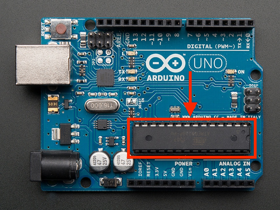
Arduino R3 microcontrollers to do the serial communication.
The next question was how I'd read the laser status, obviously. I found out that the status signs receive 12 Volt AC signals from the main switchbox, along individual wires corresponding to each status color. Alright, so there's my signal. I could splice the connections and read it into an analog port on the microcontroller. Well, not yet. A 12 VAC signal would set fire to the controller faster than you could say "arson", so I had to get it down to something acceptable. The Arduino controller can take as analog inputs DC voltages up to 5V, so that was my goal.
I ended up wiring a series of half-wave rectifiers to transform the AC signal to DC:
Okay, so it's not an ideal DC voltage profile (for that you'd use full wave rectification and probably add some smoothing capacitors) but it will work. The next issue is that the average DC voltage produced was around 4 V DC, with harmonic fluctuations ranging up to around three times that. I had to lower this to around a volt max. For that I used simple voltage dividers:
Where I chose the resistor values R1 and R2 to get Vout/Vin = 1 / 10. Cool.
Now everything was planned out -- time for some soldering. Here's the box that intercepted the cable, half-wave rectified each individual status wire and divided their voltages. The final voltage signals were set as inputs to the microcontroller's analog ports, and I programmed it to determine which status wire had an active voltage (determining the status sent to the sign) and send that signal out over bluetooth to the "slave" bluetooth module which I'd hook up upstairs in the office.
It looks messy because it is, but hey it works.
That's better.
So now I had this unit sending out repeatedly "g", "y", or "r" over bluetooth depending on the status. The next step was to intercept the signal with the other bluetooth module and program a controller to light up the sign accordingly. I gutted the old sign I found, wired in some LEDs, and attached everything together:
The LED rows were wired to digital outputs on the controller, and the bluetooth (attached on the bottom) read in its signal to the controller's serial port. I programmed the controller to light up the LEDs based on whether the bluetooth module received "g", "y", or "r". If the bluetooth connection is lost, the sign's programmed to flip out and light up all the LEDs while attempting to re-establish the connection.
And, here it is in action: a functionally wireless laser status sign that you could carry around (with a 9V battery) and always know how safe to feel.
The only thing it's missing is the high pitched whining while it's on "DANGER", which I might just go without.
Bluetooth is a pretty awesome protocol, and you can do things a lot more elaborate than this with it. Something I want to try out is setting up some solid state relays to turn on/off lights in my house from my cellphone with an android app communicating over bluetooth. One of these days.


