
Lately I've taken to building a vacuum tube amplifier for my guitar from essentially scratch, and I'm planning to post my progress on this site. These run on the antiquated (in age but not sound), analog amplification tubes that were ubiquitous in technology before the advent of integrated electronics. Here's a photo of one from Wikipedia:

Their function, put plainly, is to take an electronic signal and make it bigger. You can imagine that's a pretty useful tool, and it definitely was. Here's a photo of one of the first electronic computers. Yea, those are all vacuum tubes. Since the output of an electric guitar is a small electric signal, guitar amps were based on this technology. Nowadays we have digital electronics and tiny integrated circuits that are cheaper, easy to mass produce, more efficient, and that run on substantially lower voltages. So why in the gods' names would you want to use a vacuum tube in the 21st century?

It's not entirely a hipster thing: since the two methods amplify the sound in different ways, the amplified sound has distinct (albeit subtle) differences, and it's a preference of that sound and the charm of analog, accessible technology that's responsible for the huge number of musicians buying (or if you're a hobbyist with a deathwish like me, building) these amps.
I'll make a post later about the differences in sound, this post is getting a bit long.
So, what exactly are they and how do they work? It's not all that simple to explain, as it turns out, but here's a short spiel. Inside the glass tube are a few metal structures. Step one is to heat up the metal filament (or "cathode") really hot by sending current through it. When you heat them up to 800-1100°F, the electrons in the metal become so energetic that they jettison off.

So what happens next? Well if there were air in the tube, the electrons would scatter with the air and quickly lose all that energy we gave them, so to give them enough range to be useful, the tubes are pumped out to vacuum. Now alright, we've got electrons leaving a filament. There's also a piece of metal called the "anode," which is charged to really high voltages, high enough and with the right polarity to attract the electrons. With just those two components existing, what we get is a pretty constant stream of electrons leaving the filament and being attracted and absorbed by the cathode. You can then measure what effect the current is having on the cathode by measuring the voltage across it, but in our current setup nothing's changing.
So now we insert another metal structure between these two, called the grid. This is the star of the show, as it both transmits the signal you want to amplify (in my case sound) and by doing so leads to signal amplification. We expose the grid to a very high negative voltage (remember the anode's positive), up to the point where the electrons leaving the filament, when encountering the grid on the way to the cathode, are repelled by the grid's negative charge, and never make it to the anode. If we were to measure the current after the anode, we'd find it nil.
At this precipice, we add to that negative voltage the voltage of the sound, which affects the resulting charge of the grid in such a way that electrons are allowed to make it through the grid and to the anode, creating a current that's representative of the sound voltage we attached to the grid, and the signal is also (being the important bit) amplified! The voltage that represented the sound going into the grid is now reproduced on the anode, with higher amplitudes.
Now the details of these processes are obviously more complicated, and most tubes are more advanced (usually you have three separate grids between the anode and cathode), but I'm not trying to write a textbook on signal amplification and I probably couldn't anyway! If you'd like to read a book on these, I'd recommend this one by Megantz and Leyva (especially if you're considering building one of these amps) -- it assumes a bit of knowledge about physics, but it's damned practical and teaches you how to use the tubes' load graphs to design your own system.
Like I mentioned, I'm beginning to build a (relatively simple) amplifier based on this technology, having taken the schematics from ax84.com. The base design is called High Octane, engineered for an emphasis on power and filthy overdrive, and it's pretty damned easy to customize for your own preferences as to the gain properties, controlling what your "tone" controls are actually doing, and adding effects options. Below is the base schematic that I'm using to build it.

The parts are still arriving in the mail, so in the meantime I've been working on an accurately scaled design for the chassis on Google Sketchup (in the image below). In addition to looking badass, there are some considerations on the relative orientation of various components in order to minimize signal noise that occurs when pieces start talking to each other when they shouldn't. The first order of business will be drilling all the holes in the aluminum and then getting to some serious painting. Yea, the high voltage symbol's a bit juvenile, but I love it.

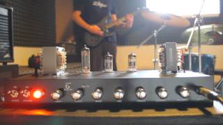
This amplifier will use two pre-amp tubes and one power tube, powered by a beefy transformer and running through a jungle of resistors and capacitors. Here are some photos of other peoples' builds for similar amps, and you should compare that to a modern-day amp that uses all integrated electronics, like this one.
My next post will probably be some photos from the drilling process and painting process, though I'm hoping to get to the electronics by next weekend.
I guess I should add a disclaimer, while I'm at it:
DISCLAIMER: DON'T FUCK WITH HIGH VOLTAGE.
No comments:
Post a Comment